Electronic Stability Control Testing

HomeElectronic Stability Control Testing


With the recent introduction of mandatory fitment of ESC systems to passenger vehicles, manufacturers are faced with ever increasing investment in advanced testing equipment.

The documentation that describes test standards FMVSS126 (US) and ECE R13H (EU) gives an indication of the type of equipment required to successfully undertake the necessary procedures.

VBOX test equipment is suitable for conducting sine with dwell tests without the need for ride height sensors or accelerometer packs, and can also be integrated with steering robots for consistent testing.

The 100Hz VBOX 3i, coupled with an IMU, provides highly accurate speed, distance, heading, and yaw rate measurement at significantly lower cost than the combination of accelerometers, ride height sensors and radar.

Additionally, the margin for error is lower when using VBOX as only a single integration is required to accurately measure lateral displacement, thanks to the very accurate speed and heading measurements provided.

Left: The VBOX 3i with IMU provide a stable base for the ABD SR60 steering robot Right: Complete technical setup, as fitted to a Honda Civic Type-R
KEY FEATURES
  • Cost effective when compared to traditional ESC testing products
  • Suitable for use in FMVSS126 and ESC R13H standards
  • Compatible with steering robots via CAN
  • Very high accuracy of speed and heading measurements
  • Free Analysis Software
  • Real-time output of all measured parameters
  • Easy and simple to install


MEASURED PARAMETERS
  • Speed (0.1km/h RMS)
  • Heading (0.1°)
  • Yaw rate (0.014˚/s)

FREE ANALYTICS SOFTWARE

VBOX Test Suite analysis software can be downloaded for free by all VBOX customers. Its intuitive interface is accessible for all users from engineer to test driver, making the process of recording and analysing your test data as quick and easy as possible.

Application-specific plugins enable you to complete your tests more efficiently than ever before, whether you are working in autonomous validation, vehicle development, certification, homologation, benchmarking or dynamics.

Using a clean workspace, multiple data sets can be compared and simultaneously examined. It does this by using separate tabs for each test, enabling you to compare different vehicles or set-ups without having to reset your test parameters each time, or search through multitudes of data on a single screen.

The software also uses context sensitive menus to make it easy for you to manage your data and can be used in either ‘Offline’ mode, for post-test analysis, or ‘Online’ mode so you can see your data in real-time.

COMPATIBLE WITH STEERING ROBOTS

Racelogic have teamed up with Anthony Best Dynamics to provide a comprehensive solution for engineers to carry out tests, which require precise and repeatable control. The high torque and steering wheel speed required to perform ESC testing means that a robot such as the ABD SR60 is essential.

ABD take the VBOX CAN output for speed, heading, yaw and roll rate at 100Hz and feed it into the robot which conducts and guides the whole test.

Firstly the car is ‘characterised’, by determining the necessary steering angle to achieve the required amount of lateral g (known as a ‘Slowly Increasing Steer‘ procedure). The actual Sine with Dwell test is then performed with increasing yaw and displacement, on both right and left turns.


VBOX 3i

The 100Hz data logger has the ability to utilise data from a RACELOGIC IMU to improve all parameters measured in real-time – improving accuracy and noise levels, and enhancing the dynamic response to velocity.

IMU integration also combats satellite drop out up to 10 seconds without lock.


Inertial Measurement Unit

Racelogic’s IMU (RLVBIMU04) provides highly accurate measurements of pitch, roll, and yaw rate using three rate gyros, as well as x, y, z acceleration via three accelerometers.


VBOX to IMU Cable

The latest RACELOGIC IMU (RLVBIMU04) uses serial communication instead of CAN and connects to the 25 Way input of the VBOX via CAB119.

TEST PROCEDURES

The NHTSA (USA National Highway Traffic Safety Association) ruling requires the inclusion of ESC on all new passenger vehicles and trucks with a gross vehicle weight rating of 4,536 Kg or less. The FMVSS126 test procedure evaluates the performance of Electronic Stability Control (ESC) systems with the goal of reducing vehicle rollover accidents.

The FMVSS126 procedure simulates a driver steering past a sudden obstacle and then trying to get back on course. For most drivers a car without ESC will roll or spin. The test measures the responsiveness of the steering system and the ability for the vehicle to correct and return to the original course.

To pass, the vehicle must deviate at least 1.83 metres from the original centreline path within 1.07 seconds of the first steering input being applied, to show that it is responsive to steering input. The yaw rate ratios of the vehicle are also measured and compared at set time intervals, to prove that the ESC can control the heavy yaw manoeuvre and does not let the vehicle spin.

Slowly Increasing Steer

The simulation test procedure begins with a “Slowly Increasing Steer Test” intended to determine the steering wheel angle A associated with a lateral acceleration of 0.3g for a speed of 80 km/h with the steering angle increasing at a rate of 13.5 deg/s. When performed via physical testing, three tests are repeated for counter-clockwise steering up to a lateral acceleration of 0.5 g; the steering angle at exactly 0.3 g’s of lateral acceleration is calculated using linear regression for each test, and the three results are averaged. The sequence is repeated for clockwise steering, and the absolute angles obtained in the two directions are averaged to obtain A.

Sine with Dwell

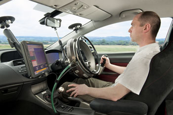
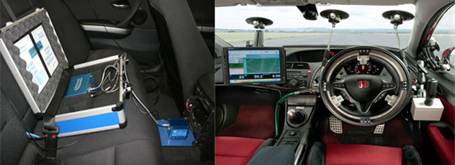
A “sine with dwell” test involves bringing the vehicle to a speed slightly above 80 km/h with no steering or braking, letting it coast in the highest gear to 80 km/h, and then using a robot to apply a steering control with the shape of a wave.

Two series of tests are conducted. In the first test, the waveform is scaled by 1.5*A. If the vehicle passes the test, then the amplitude is increased for the next test by an increment of 0.5*A. The final run in a series is reached when the amplitude is greater than 270 deg. (Also, if the amplitude delta is greater than 300°, then the amplitude for the final run is reduced to 300 deg).


The success or failure of each test in the series is based on the vehicle state at three specific times relative to the start of the steering:

If the gain is 5.0 or greater, then a lateral displacement check is made at 1.07 sec. The lateral displacement of the vehicle mass centre must be 1.83 m (6 ft) or greater relative to the start of the test for vehicles with GVW of 3,500 kg or less. If the displacement is less, then the vehicle fails the test. For vehicles with GVW greater than 3,500 kg, the required lateral displacement is 1.52 m (5 ft).

A peak yaw rate is obtained for the test. The instant yaw rate 1.0 sec after the steering stops is compared to the peak rate, and must be 35% of the peak rate or less. If the instant yaw rate is higher than 35% of the peak yaw rate, then the vehicle fails the test.

The instant yaw rate 1.75 sec after the steering stops is compared to the peak rate, and must be 20% of the peak rate or less. If the instant yaw rate is higher than 20% of the peak yaw rate, then the vehicle fails the test.

pattern
https://www.zenmicrosystems.co.in/wp-content/themes/blake/
https://www.zenmicrosystems.co.in//
#ef3e35
style3
paged
Loading posts...
/home/zenmicrosystemsc/public_html/
#
on
none
loading
#
Sort Gallery
https://www.zenmicrosystems.co.in/wp-content/themes/blake
on
no
off
ENTER YOUR EMAIL HERE!
off
off