VBOX systems are suitable for the following test scenarios:
TESTING TO EURO NCAP
The Euro NCAP standard defines three test procedures:
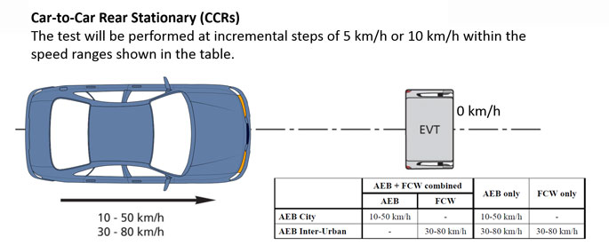
- Car-to-Car Rear Stationary (CCRs)
Vehicle travels towards another stationary vehicle
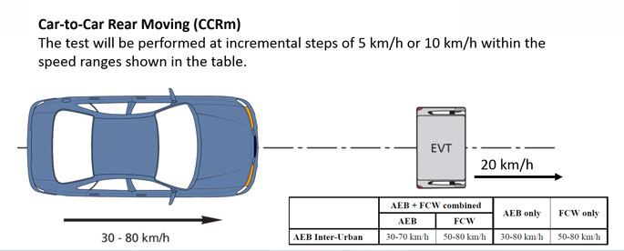
- Car-to-Car Rear Moving (CCRm)
Vehicle travels towards another vehicle travelling at constant speed
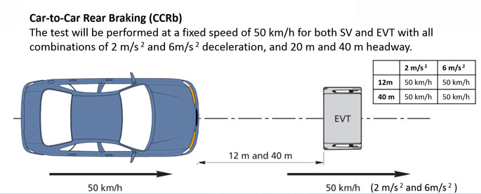
- Car-to-Car Rear Braking (CCRb)
Vehicle travels towards another vehicle travelling at constant speed and then decelerates
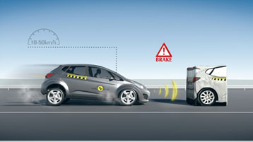
Autonomous Emergency Braking (AEB) systems that work at lower speeds, referred to as AEB City, only have to be tested for CCRs. AEB systems that work at higher speeds, AEB Inter-Urban, need to be tested in all three test scenarios.
Instead of a target vehicle the Euro NCAP soft target (EVT) should be used (see picture).
The subject vehicle follows a soft target (EVT) towed by another vehicle, with a range of closing velocities.
Once the test conditions are met, the towing vehicle brakes at a constant deceleration whilst the test vehicle’s Autonomous Emergency Braking (AEB) system should detect this and apply the brakes.
In order to perform this procedure efficiently, robots should be used. VBOX test systems are compatible with ABD steering and pedal robots, and VEHICO systems.
The test starts when the TTC is 4s and the SV and EVT have been accelerated to the specified test speed. Test is valid when the below conditions are met.
- Speed of SV: Test speed +1.0 km/h
- Speed of soft target: Test speed ±1.0 km/h
- Lateral deviation from test path: 0 ± 0.1 m
- Yaw velocity: 0 ±1.0 °/s
- Steering wheel velocity: 0 ±15.0 °/s
- Relative distance between SV and soft target (CCRb): 12 m or 40 m ± 0.5 m
The test ends when the SV’s speed is 0 km/h, smaller than the speed of the soft target or there has been contact between SV and soft target.
TESTING TO NHTSA NCAP
Three test procedures are specified in the NHTSA NCAP Forward Collision Warning Confirmation
Test:
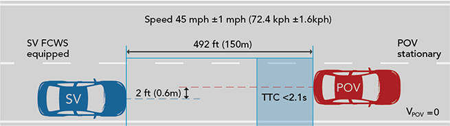
1) Subject Vehicle (SV) encounters stopped Principal Other Vehicle (POV) on a straight road
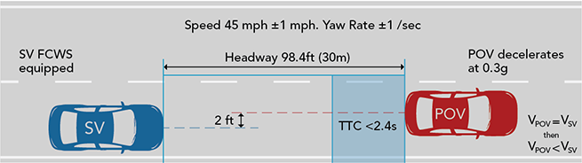
2) SV encounters decelerating POV
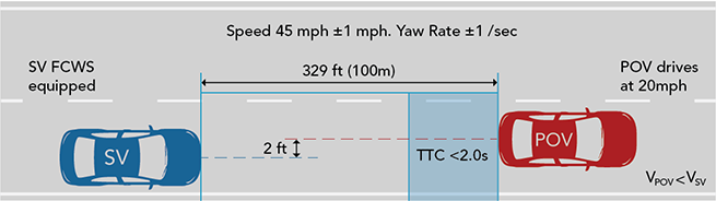
3) SV encounters slower POV
Test 1 – Stationary POV
This test evaluates the ability of the FCW function to detect a stopped lead vehicle. In order to pass the test, the FCW alert must be issued when the time-to-collision (TTC) is at least 2.1 seconds.
The FCW system must satisfy the TTC alert criteria for at least five of the seven test trials.
Test 2 – Decelerating POV
The subject vehicle (blue) follows the target vehicle (red) at a constant time gap. The test evaluates the ability of the FCW to recognise a decelerating lead vehicle and to issue an alert to SV driver in a timely manner.
In order to pass the test, the FCW alert must be issued when the time-to-collision (TTC) is at least 2.4 seconds.
Test 3 – Slower POV
The test evaluates the ability of the FCW to recognise a slower lead vehicle being driven at a constant speed and issue a timely alert.
In order to pass the test, the FCW alert must be issued when the time-to-collision (TTC) is at least 2 seconds.
TESTING TO ISO 15623
ISO 15623 defines three test procedures:
1) Detection Zone Tests
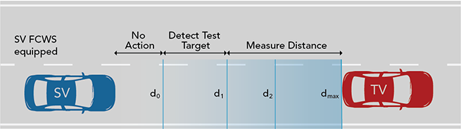
Determines if the FCW system detects a test target when it’s in the system’s detection range and measures the separation when it’s in measurement range.
2) Warning Distance Accuracy Tests
Determines if the FCW systems issues a warning at the distance it states to do it.
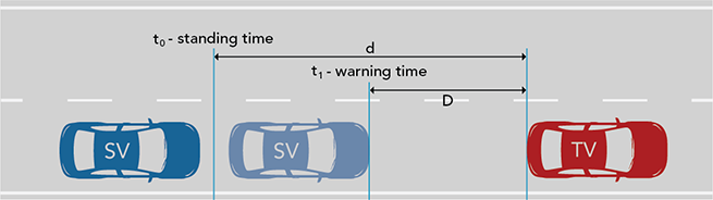
The subject vehicle is driven towards the target at the maximum vehicle speed at which the FCW system is able to operate. The warning distance is measured at the minimum detectable distance (t0), and when the warning is issued (t1). The distance at which the warning signal occurred (D) is then compared to the warning distance specified by the manufacturer.
3) Target Discrimination Tests
Involves two or more obstacle vehicles and determines whether the FCW system is able to identify the (closest) vehicle in the subject vehicle’s trajectory.
3a) Straight road longitudinal discrimination
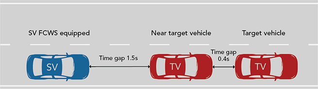
The subject vehicle follows two target vehicles at the maximum speed the FCWS is capable of operating. The nearer target vehicle shall not mask the other.
The subject vehicle (blue) accelerates until it produces a preliminary warning, then decelerates until warning stops and keeps speed. Then, the nearer target vehicle decelerates until the subject vehicle produces a warning.
The test is successfully fulfilled if the subject vehicle has produced a warning.
3b) Straight road lateral discrimination
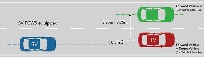
Two vehicles (red/ green) travel alongside at the maximum speed the FCWS is capable of operating. The spacing between the longitudinal centrelines of the cars is 3.5m ± 0.25m.
The subject vehicle (blue) follows the target vehicle (red) at the same speed. The lateral displacement between subject vehicle and the target vehicle shouldn’t be more than 0.5m measured from their longitudinal centreline.
First the forward vehicle decelerates (green). Then, the target vehicle (red) decelerates until it’s in the detection range of the subject vehicle’s FCWS.
The test is successful when the subject vehicle issues a warning signal for the second scenario and doesn’t react to the first.
3c) Curved road lateral discrimination
The same test is conducted on a circle or a sufficient part of a circle with a curve radios specified by the ISO systems classifications.
The test is successful when the subject vehicle doesn’t issue a warning when the forward vehicle (green) decelerates, and issues a preliminary collision warning when the target vehicle (red) decelerates.

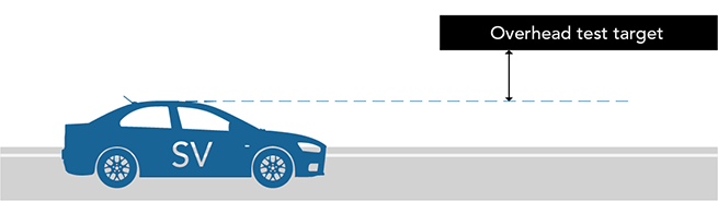
3d) Overhead discrimination
A test target which may cause false warnings is installed at a height defined according to the road standard of each country. The subject vehicle approaches the test target.
The test is successful if the subject vehicle has not produced a warning.