Adaptive Cruise Control

HomeAdaptive Cruise Control

With real-time measurement of parameters from up to four vehicles and at better than 2 cm positional accuracy, the VBOX testing system allows manufacturers to easily verify the effectiveness of their Adaptive Cruise Control system.

At the core of the system is RACELOGIC’s flagship data logger, the VBOX 3i RTK (VB3iSLR), connected via radio telemetry to an RTK Base Station or to another VBOX 3i RTK acting as a moving base.

  • Measured Parameters
  • Multiple Target Capability
  • Open Road Testing
  • Video Integration
  • Free Analysis Software
  • ACC Warning Signals
  • Multiple Contact Points


MEASURED PARAMETERS
  • Speed of target and subject vehicle
    (0.1km/h RMS)
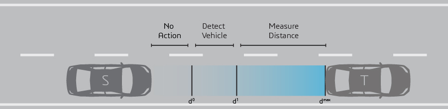
  • Separation time (0.05s)
  • Longitudinal separation (0.02m RMS)
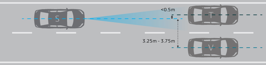
  • Lateral separation (0.02m RMS)
  • Yaw rate for target and subject vehicle
  • Angle to target vehicle (0.1º RMS)
  • ACC warning signal output


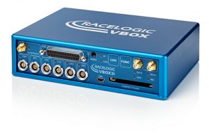
For a list of all standard GPS data channels and accuracies that are also measured please refer to the VBOX 3i RTK product page.


MULTIPLE TARGET CAPABILITY

The ‘Multiple targets’ feature of the ACC test equipment is capable of calculating parameters from three target vehicles and the lane at the same time.


OPEN ROAD TESTING

By substituting the DGPS Base Station with a specially configured VBOX 3i RTK, our MOVING BASE test setup allows users to test and verify active safety systems outside the test track.

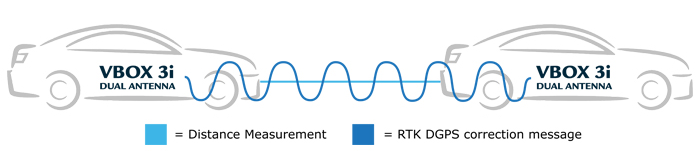
  • Conduct realistic testing amongst other road users and roadside architecture
  • Test over a large area
  • Measure with relative positional accuracy between subject and target vehicle under 5 cm
  • Maintain RTK lock between VBOX units with up to 600m of vehicle separation in good conditions
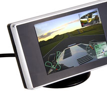


VIDEO INTEGRATION

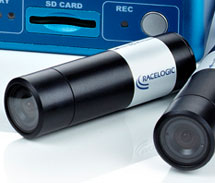
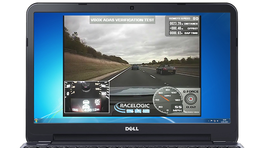
When used in conjunction with a VBOX video system, the measured parameters can be graphically overlaid in real-time onto the recorded video, providing a clear visual reference to the performance of the test.

Graphical overlay is totally user configurable and can be easily altered to present relevant information according to the tests being conducted.


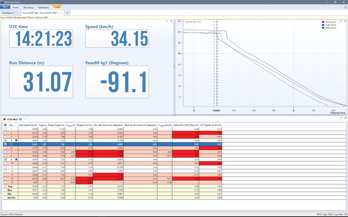
FREE ANALYSIS SOFTWARE

VBOX Test Suite has been developed to make the process of analysing your test results as quick and clear as possible by combining a clean layout with the ability to compare sets of data simultaneously using multiple test conditions.

It does this by using separate tabs for each test, enabling you to compare different vehicles or set-ups without having to reset your test parameters each time, or search through multitudes of data on a single screen.

The software also uses context sensitive menus to make it easy for you to manage your data and can be used in either ‘Offline’ mode, for post-test analysis, or ‘Online’ mode so you can see your data in real-time.


ACC WARNING SIGNALS

If the vehicle carries the ACC operation data on its CAN Bus, this can be simultaneously logged (and displayed in video if a VBOX video logger is also being used) alongside that of the GPS data, giving you an exact comparison between relative vehicle position and onboard strategy data.

If you cannot use the vehicles’ own CAN system, an AVAD3 audio & visual detector from DTC Solutions can be used alongside VBOX to record when an ADAS system has become active. The AVAD3 is capturing acoustic and optical alerts and signals generated by the vehicle’s advanced driver assistance system. It produces a CAN or digital signal when recognising changes of the shapes and colors of defined icons or when audible signals are identified. The output of the AVAD3 can then be used by the VBOX to log the exact moment the vehicle safety message is displayed to the driver.

MULTIPLE CONTACT POINTS

To assist in the testing of ADAS applications such as Blind Spot Monitoring and Rear Cross Path Detection, it is now possible to ‘map’ the shape of vehicles using a survey pole, antenna, and VBOX Manager. Up to twenty-four points around the vehicle bodies can be surveyed, and the ‘shape’ of each car can be stored for later use. As the test is conducted, the distance of the closest contact points between the vehicles is calculated to +/-2cm accuracy, automatically switching to the nearest contact points as they change with the car’s relative positions.

This allows for multiple procedures to be completed without having to reconfigure for individual contact points – such as moving from right rear to left rear flank during blind spot testing. This video demonstrates how the system works:

VBOX TEST SYSTEMS

Adaptive Cruise Control testing and validation can be conducted on the test track using a static DGPS Base Station, or via the Moving Base solution. A typical RACELOGIC test system comprises of:


VBOX 3i RTK (x2)
100Hz GPS data logger in both the subject and target vehicle

Each RLVB3iSLR logs up to 64 channels simultaneously (excl. standard GPS).


VBOX CAN Hub
The RLVBCANHUB allows for additional external modules to be connected to a VBOX 3i. Its footprint is the same as the VBOX 3i, so it can sit neatly underneath.


Video VBOX Pro (optional)
When used in conjunction with Video VBOX or VBOX HD, the measured parameters can be graphically overlaid in real-time onto the recorded video.


Several Radio Pairs
Used to transmit/receive differential correction signals, for VBOX to VBOX or VBOX to PC communication.

There are a variety of telemetry systems available, employing a range of frequencies.


Tripod for GPS Antenna
The VBBSTRIPOD2 enables the Base Station GPS Antenna to be mounted at a suitable height, at a non-permanent track side location.


Preview Monitor (optional)
The Preview Monitor comes with the Video VBOX and enables you to align the cameras on the vehicle.


DGNSS Base Station RTK
Enables a positional accuracy of ±2cm.

The RLVBBS4RG comes with antenna and is able to transmit RTCM, CMR, RTCMV3 or RL proprietary (2cm) correction messages via radio.


Survey Trolley (optional)
The Survey Trolley Kit allows for the accurate surveying of a lane edge, necessary when performing ACC tests along a curved lane.


Camera Mounting Arm (optional)
Adjustable mounting arm for use with video cameras.

VBOX systems are suitable for the following ACC validation test scenarios:

  • Steady state distance
  • Approaching convoy
  • Acceleration / deceleration in convoy
  • Overtaking from steady state
  • Lane changing obstacle vehicle
  • Overtaking after approach
  • Stop and go
  • Cornering
ISO 15622

The ISO 15622 standard contains the basic control strategy, minimum functionality requirements, basic driver interface elements, minimum requirements for diagnostics and reaction to failure, and performance test procedures for Adaptive Cruise Control (ACC) systems.

The standard defines three test procedures:


Target acquisition range test

VBOX records the ACC’s commands via CAN and displays them live during testing. The vehicle separation is measured with a positional accuracy of better than 2cm.

S = Subject Vehicle (Equipped with ACC)
T = Target Vehicle

Target Discrimination Test

The VBOX constantly measures the distance to the target vehicle which verifies that the ACC has locked onto the correct target. Video VBOX can be used to prove that the 2nd forward vehicle has been passed without affecting the separation range between subject and target vehicle.

S = Subject Vehicle (Equipped with ACC)
T = Target Vehicle
V = Forward Vehicle


Curve Capability Test

VBOX ACC test equipment will measure the time gap and separation between both vehicles accurate to 2cm. For high accuracy sampling of the curved lane we have developed the survey trolley, a line mapping rover wheel which comes with a custom rucksack containing radios, antenna and groundplane.

S = Subject Vehicle
T = Target Vehicle


pattern
https://www.zenmicrosystems.co.in/wp-content/themes/blake/
https://www.zenmicrosystems.co.in//
#ef3e35
style3
paged
Loading posts...
/home/zenmicrosystemsc/public_html/
#
on
none
loading
#
Sort Gallery
https://www.zenmicrosystems.co.in/wp-content/themes/blake
on
no
off
ENTER YOUR EMAIL HERE!
off
off