Pass-By Noise Testing

HomePass-By Noise Testing

Certification of vehicle noise emissions for passenger vehicles, motorcycles and light trucks is achieved by measuring external sound levels according to procedures defined by international standards such as ISO 362.

ISO 362 defines the pass-by test procedures for measuring noise emitted by accelerating road vehicles, and the ECE R41 (motorcycle), R51 (automobile) and R138 (quiet vehicles, e.g. electric) standards regulate the limits of the vehicle exterior noise.

Racelogic is providing Pass-By (or Drive-By) Noise testing equipment to log channels such as engine RPM, vehicle velocity and maximum vehicle exterior noise to the accuracy requirements of this standard. The system can be installed in the vehicle for R51 and R138, allowing the driver to operate the measurement equipment without the need for additional operatives.

Additionally, the VBOX Test Suite software has been enhanced to include Pass-By Noise plugins allowing development programs to be completed to the ECE R41/ R51/ R138 standards, prior to homologation testing.


The software allows you to enter session-specific information that defines test conditions and vehicle details, including the requirement of kerb mass, power, idle rpm and rated engine rpm. This information is automatically saved to the log file and so only needs to be entered once; it can also be exported for use in another file, saving setup time.

KEY FEATURES
  • Simultaneous logging of speed, acceleration, engine RPM, and throttle position
  • Sound Pressure Level also recorded with above parameters when used in conjunction with specialist microphones
  • Multiple test passes possible with one operative only
  • Reports are produced for each style of test
  • High accuracy distance measurement negating the need for multiple light-barrier trigger systems
  • VBOX Test Suite Software can be used for viewing/analysing live data or via post processing
  • Live weather data from a Davis Vantage Pro 2 can also be logged simultaneously
  • Allows for compliance testing to ECE R41 (motorcycle), R51 (automobile) and R138 (quiet vehicles, e.g. electric) standards

MEASURED PARAMETERS
  • Sound pressure level
    (WOT, Steady speed, ASEP)
  • Speed & RPM
    (Start, Microphone location, Test end)
  • Average acceleration across test area
  • Calculated reference accelerations, power-to-mass ratio as stipulated
  • Pass/fail between test results and calculated values
SOFTWARE

VBOX Pass-By Noise software is a free plugin for VBOX Test Suite. The Pass-By Noise plugin allows for development programs to be completed to the ECE R41 (motorcycle), R51 (automobile) and R138 (quiet vehicles, e.g. electric) standards, prior to homologation testing.

The video below demontrates a pass-by noise test being carried out using VBOX Test Suite.

R51/R138 (AUTOMOBILE) TESTING

R51/R138 – Single Mini Input Module Setup

  • 1 x 100 Hz GPS Data Logger (RLVB3i)*
  • 1 x Laser Light Barrier Kit (RLACS189)**
  • 2 x 5 Ahr Li Ion battery pack (RLACS112L)
  • 1 x Vehicle Telemetry Radio (RLRTM24MBS)
  • 1 x Road side Telemetry Radio (RLRTM24MBC)
  • 1 x Mini Input Module (RLVBMIM01)
  • 2 x B&K 2250 SLM DC output Cable to Mini Input Module (RLCAB143)
  • 1 x PC or Tablet
  • 1 x Optional cables if using both an MFD and CAN Input from test vehicle (RLCAB081)
  • 1 x Rugged roadside equipment case (RLACS252)


R51/R138 – Dual Mini Input Module Setup

  • 1 x 100 Hz GPS Data Logger (RLVB3i)*
  • 1 x Laser Light Barrier Kit (RLACS189)**
  • 2 x 5 Ahr Li Ion battery pack (RLACS112L)
  • 1 x Vehicle Telemetry Radio (RLRTM24MBS)
  • 2 x Road side Telemetry Radio (RLRTM24MBC)
  • 2 x Mini Input Module (RLVBMIM01)
  • 2 x B&K 2250 SLM DC output Cable to Mini Input Module (RLCAB143)
  • 1 x PC or Tablet
  • 1 x Optional cables if using both an MFD and CAN Input from test vehicle (RLCAB081)
  • 2 x Rugged roadside equipment case (RLACS252)

*The R138 regulation requires conducting the tests in the forward and reverse direction. When using a VBOX 3i Dual Antenna, the VBOX Test Suite R138 Plug-in can automatically detect the direction of travel of the vehicle and categorise the results for each prescribed test direction and speed. A single antenna VBOX 3i can still be used, however, the direction of travel will be assumed to always be in the forward direction.

**Optional DGPS radio can be used as a substitute for the Laser Light Barrier (RLACS189), however a VB3iSLR and RTK Base Station are required.


ECE R41 (MOTORCYCLE) TESTING

R41 – Single Mini Input Module Setup

  • 1 x 100 Hz GPS Data Logger (RLVB3i)
  • 1 x Laser Light Barrier Kit (RLACS189)*
  • 2 x 5 Ahr Li Ion battery pack (RLACS112L)
  • 1 x Vehicle Telemetry Radio (RLRTM24MBS)
  • 1 x Road side Telemetry Radio (RLRTM24MBC)
  • 1 x PC or Tablet
  • 1 x Rugged roadside equipment case (RLACS252)
  • 1 x Rugged motorcycle equipment case (RLACS253)
  • 1 x Mini Input Module (RLVBMIM01)
  • 2 x B&K 2250 SLM DC output cable to Min Input Module (RLCAB143)
  • 2 x Optional cables if using both an MFD and CAN Input from test vehicle (RLCAB081)


R41 – Dual Mini Input Module Setup

  • 1 x 100 Hz GPS Data Logger (RLVB3i)
  • 1 x Laser Light Barrier Kit (RLACS189)*
  • 3 x 5 Ahr Li Ion battery pack (RLACS112L)
  • 1 x Vehicle Telemetry Radio (RLRTM24MBS)
  • 2 x Road side Telemetry Radio (RLRTM24MBC)
  • 2 x Mini Input Module (RLVBMIM01)
  • 2 x B&K 2250 SLM DC output Cable to Mini Input Module (RLCAB143)
  • 1 x PC or Tablet
  • 1 x Multi-Function Display is an optional item for R41 Testing (RLVBDSP03-24)
  • 2 x Optional cables if using both an MFD and CAN Input from test vehicle (RLCAB081)
  • 2 x Rugged roadside equipment case (RLACS252)
  • 1 x Rugged motorcycle equipment case (RLACS253)

*Optional DGPS radio can be used as a substitute for the Laser Light Barrier (RLACS189), however a VBOX 3i RTK and RTK Base Station are required.

ISO 362 AND ECE R41/ R51

ISO 362 defines the pass-by test procedures for measuring noise emitted by accelerating road vehicles, while the ECE R41 (motorcycle) and R51/R138 (automobile) standards regulate the limits of the vehicle exterior noise.

The Pass-By Noise test procedure involves an open-throttle acceleration test and a constant speed test (only for vehicles with a power-to-mass ratio higher than 25). ISO 362:2014 specifies 50 km/h at the microphone, to which the Additional Sound Emission Provision (ASEP) adds four extra runs past the microphones for every gear ratio – 24 tests for a 6-speed car.

The new type-approval procedures are designed to ensure that the vehicle’s sound levels do not significantly differ from the ISO pass-by test result under typical on-road driving conditions, at a broader range of speeds.

R138 ELECTRIC VEHICLE PASS BY NOISE

With electric vehicles being virtually silent at low speeds – typical of urban areas with lots of pedestrians and vulnerable road users – the new R138 regulation ensures that a basic sound level emanates from this type of automobile as a safety measure.

It follows the same procedures for R41 and R51, but introduces a minimum sound pressure level as well as the existing 75dBA maximum.

ACCELERATION TESTS

This test require the driver to apply full throttle between the lines AA’ and BB’. The selection of gear ratio depends on the vehicles acceleration potential as specified in the standard. The test must be repeated several times to prove a consistent average value.

CONSTANT SPEED TESTS

The constant speed test shall be carried out with the same gear(s) as specified in the acceleration test and a constant speed of 50 km/h ±1 km/h between AA’ and BB’. The tests must be repeated several times to prove a consistent average value.

ASEP

ASEP requires four additional runs past the microphones for every gear ratio. These are designed to capture the vehicle’s noise at four different speeds for every gear, from the lowest – a 20 km/h entry speed (10 metres before the microphone), up to an 80 km/h exit speed (10 metres after the microphone).

TEST SETUP

Although the test pass criteria are different between R41 and R51 testing, the test track layouts are the same as shown in Figure 1.

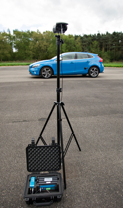
Microphones placed within the test area output to a VBOX Mini Input Module using the DC voltage output of the microphones. The Mini Input Module continuously transmits the converted sound readings to the VBOX 3i GPS data logger mounted on the test vehicle at 100 Hz using 2.4 GHz Telemetry Radios.

If using a laser light, it should be attached to the side of the vehicle under test and a reflective strip is placed a distance before the start test line AA’ to define the start and end lines of the test as shown in Figure 1.

These offset distances are input into the VBOX Test Suite Pass-by Noise plugins for the analysis to occur. You can use the system in both directions, just install another reflective strip on the other end of the test track so when you drive in the opposite direction it will also trigger.

Instead of using a laser light barrier to trigger the start of the test, a VBOX 3i RTK (VB3iSLR) can be used to set the start and finish lines when used with an RTK Base Station or NTRIP solution. This means that the test vehicle doesn’t have to come to a stop between test runs.

The R138 regulation requires conducting the tests in the forward and reverse direction. When using a VBOX 3i Dual Antenna, the VBOX Test Suite R138 plug-in can automatically detect the direction of travel of the vehicle and categorise the results for each prescribed test direction and speed. A single antenna VBOX 3i can still be used, however, the direction of travel will be assumed to always be in the forward direction.

pattern
https://www.zenmicrosystems.co.in/wp-content/themes/blake/
https://www.zenmicrosystems.co.in//
#ef3e35
style3
paged
Loading posts...
/home/zenmicrosystemsc/public_html/
#
on
none
loading
#
Sort Gallery
https://www.zenmicrosystems.co.in/wp-content/themes/blake
on
no
off
ENTER YOUR EMAIL HERE!
off
off