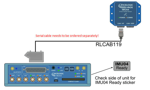
VBOX Inertial Measurement Unit

HomeVBOX Inertial Measurement Unit

Racelogic’s Inertial Measurement Unit (RLVBIMU04) provides highly accurate measurements of pitch, roll, and yaw rate using three rate gyros, as well as x, y, z acceleration via three accelerometers. The CAN based unit is temperature compensated and has improved calibration and stability.

The RLVBIMU04 is designed for use either as a standalone sensor with simple connection and configuration via the CAN bus interface, or for use with VBOX GPS data loggers.

When used in conjunction with VBOX 3i, data from the IMU can be seamlessly integrated with GPS to produce pitch and roll angle accurate to 0.06˚ (RMS) as well as smoother velocity data. This ensures GPS data even when satellite reception is interrupted.

The IMU is constructed with a splash proof casing, which is rated to a limited ingress IP rating of IP67*, making it ideal for use on boats or in harsh environments, as well as automotive testing.

Using synchronous 16bit sampling for each of the internal sensors provides a high degree of accuracy, with yaw rate resolution typically 0.014 degrees per second and acceleration resolution down to 0.15 mg.

*providing unused connectors are fitted with Lemo bungs (RLACS080)

  • Yaw rate range ±450˚/s
  • Acceleration range ±5 g in each axis
  • Internal temperature compensation
  • Yaw rate resolution 0.001˚/s
  • Acceleration resolution 0.15 mg
  • CAN Bus interface
  • Integration with GNSS for consistent and accurate data in weak/degraded satellite signal conditions
  • Splash proof: IP65 rating / IP67 rating providing unused connectors are fitted with Lemo bungs (RLACS080)
  • 0.06˚(RMS) pitch/roll accuracy and 0.5˚(RMS) yaw angle accuracy when used in conjunction with a VBOX 3i

IMU04 vs. IMU03

The new IMU04 uses higher grade inertial sensors which have less measurement noise and a wider range. This has enabled the Kalman Filter in the VBOX3i to accurately track Pitch, Roll and Yaw angles.

 IMU04  IMU03
  Lever-arm correction  Yes  With VBOX 3i (FW 2.1+)
  Pitch/roll angle accuracy  0.06° RMS*  No
  Yaw angle accuracy  0.5° RMS*  No


GYROSCOPES (ANGULAR RATE SENSORS)

  Dynamic range  ±450°/s  ±150°/s
  Nonlinearity  0.01%  0.1%
  Resolution  0.001°/s  0.01°/s
  Bandwidth  50 Hz  40 Hz
  Noise density  0.015 °/s/√Hz  0.04 °/s/√Hz
  Bias stability  ±0.0035 °/s  ±0.3°/s


ACCELEROMETERS

 Range  ±5g  ±1.7g
 Nonlinearity  0.03 %  ±0.5% – ±2.5
 Resolution  0.15 mg  1mg
 Bandwidth  50 Hz  50 Hz
 Noise density  150 µg/√Hz  250 µg/√Hz
 Bias stability  40 µg  40 µg


PHYSICAL

 Maximum power consumption  1.7 W  1.5 W
 Typical power consumption  1.3 W  0.9 W
 Voltage  7 – 30V DC  8 – 30V DC
 Operating temperature  -20 to +70 ˚C  -30 to +70 ˚C
 IP rating  IP65 / IP67*  IP65
 Maximum ratings (shock)  Powered (0.5ms): 2000g  Powered (0.5ms): 2000g
 Dimensions  64.1 (l) x 76 (w) x 29 (h) mm  92 (l) x 88 (w) x 48 (h) mm


*providing unused connectors are fitted with Lemo bungs (RLACS080)

1) Using the Racelogic Roof Mount

The easiest and the most accurate method of mounting the IMU is by using the integral GPS antenna and IMU roof mount. The VBOX IMU roof-mounting option allows for an IMU04 to be placed directly on the vehicle roof, co-located with the GPS antenna.

The IMU is securely fastened within the machined enclosure which has a magnetic base to ensure that it stays safely in place. The antenna is placed directly above the IMU, ensuring that the data sources are being measured at the same point.

Co-locating the antenna and IMU greatly improves the performance of the Kalman filter. By putting the two together and mounting them on the vehicle’s roof there is no requirement to measure the distance between them as you do in a standard setup, and it is easier to install. With the GPS and inertial data sources coming from the same point, this critical measurement is no longer needed, leaving only the required translation to – typically – the vehicle’s centre of gravity. This method is easier and isn’t prone to human measurement error.

See datasheet for RLACS216 here.


2) Using the Racelogic Mounting Arm

If roof-mounted IMU is not possible the IMU can be fixed inside the vehicle. A flexible way to fix the IMU rigidly within the vehicle is by using the Racelogic mounting arm. The three-part telescopic handle is fully adjustable to any length between 70 and 150 cm to which another 20 cm can be added by extending a third section using the compression lever.

Both ends are fixed to an 8x13cm plate which sits on a joint to accommodate for uneven surfaces. Pressed against the IMU on the floor and the vehicle’s ceiling, the mounting prop ensures that the IMU is fixed tightly.


3) Fixed

It is possible to fix the IMU firmly to the body of the vehicle. Make sure it is mounted in the direction of travel – as shown in the image below. It is also important to mount the sensor so that it is level with the ground.

For best results, mount the IMU and GPS antenna as close to each other as possible. For example: Bolt the IMU to the seat rails and place the GPS antenna on the roof directly above.

If you are using an IMU04 or IMU03, you must measure the relative position of the antenna in relation to the IMU to within +/- 5cm. These distances must then be entered into the VBOX either via VBOX Tools > VBOX Setup or using a VBOX Manager.

IMU INTEGRATION

Survey-grade high-speed GPS is the most accurate way to measure velocity – as long as view to the sky is clear.

Problems arise when buildings or tall trees obstruct the testing ground. If the GPS signal is interrupted, dropouts cause spikes in data, which is not ideal when you are relying on a clean velocity signal.

In order to keep high GPS accuracy even where sky visibility is less than perfect, Racelogic couples data from an IMU and the VBOX 3i GPS data logger.

By blending GPS with data from an Inertial Measurement Unit, housing three gyros and three accelerometers, smoother, more reliable data is produced. The solution can deal with GPS dropouts, maintaining high accuracy. IMU integration realises the high accuracies that VBOX 3i can achieve even when external conditions are compromised, meaning that data has now become more reliable and easier to interpret.

How does IMU Integration improve the GPS data channels?

VELOCITY

IMU integration decreases the noise for a more accurate reading, and maintains a precise velocity measurement throughout the GPS drop outs.

HEADING

The heading reading here is very consistent, providing more accurate results than the GPS only data, which exhibits some noise, even in low speeds.

POSITION

When mapping vehicle position along a heavily tree lined road, the GPS signal incurs some drop outs and reflections, producing noisy position readings. However, IMU integration corrects the position measurements, creating smoother, more accurate data.

ACCELERATION

IMU Integration data provides a smoother, more accurate representation of longitudinal acceleration (measured in G-force) during an ABS brake stop.

BRAKE TESTING USING IMU INTEGRATION

Conducting brake tests on tall vehicles with long suspension travel can result in a speed overshoot of the velocity data, due to the measurements being taken at the high roof position of the GPS antenna. As the brakes are initially applied, there is a higher rate of change in velocity at the roof than there is at the vehicle’s centre of gravity (COG).

However, the integration of an IMU04 or IMU03 with a suitably upgraded VBOX 3i can be used to counteract this ‘lever-arm’ effect by placing the IMU at the COG, which measures the vehicle pitch as it brakes. This data, when combined with that from GPS, provides a compensation for the overshoot and allows for consistent brake stop testing.


The graphs below show how point A has travelled further than point B:

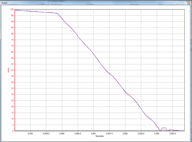
In this example of a high-dynamic brake stop, the blue trace (GPS Speed) overshoots at the initial point of brake application, and then exhibits a damped oscillation as the deceleration continues. The IMU-corrected data (red trace) accurately records the brake stop from the vehicles centre of gravity.

Counteracting the lever-arm effect will also aid test engineers when conducting high-dynamic manoeuvres other than brake stops. In slip angle measurements the speed overshoot can occur if the antenna is moving through a greater arc of travel than that of the vehicle’s centre of gravity as it corners. Procedures such as lane change manoeuvres can therefore benefit from IMU integration and lever-arm compensation.

Orange = Pitch measured by the IMU     Blue = GPS speed      Red = IIMU itegrated GPS speed
The traces between the green and red vertical lines are of a car going over a speed hump. Note how the GPS speed alters as the vehicle roof moves independently of the COG as it goes over the hump. The integrated speed logs the correct speed of the vehicle.

IMU04 used in Integration Mode (Kalman Filter)
All VBOX units purchased before Jan 2014 need to be upgraded to enable IMU04 integration.


IMU04 used in RL Module Mode
Works with any VBOX unit.


IMU04 used in a Daisy-Chain with other VBOX Modules
Works with any VBOX unit.


IMU03 in Integration or RL Module Mode
RL Module Mode works with all VBOX units, IMU03 Integration only with VBOX 3i units.


The overall performance of the Kalman Filter (IMU03 Integration) is not as good as with IMU04. IMU03 Integration will not provide lever arm correction if the firmware is not upgraded to version 2.1+, nor body attitude (pitch & roll angles).

GYROSCOPES (ANGULAR RATE SENSORS)

  • Dynamic range: ±450°/s
  • Nonlinearity: 0.01%
  • Resolution: 16 bit ADC (0.001°/s)
  • Bandwidth: 50 Hz
  • Noise density: 0.015 °/s/√Hz
  • Bias stability: ±0.0035 °/s
  • Bias repeatability (1 year): 0.5 °/s

ACCELEROMETERS

  • Range: ±5g
  • Nonlinearity: 0.03 %
  • Resolution: 16 bit ADC (0.15 mg )
  • Bandwidth: 50 Hz
  • Noise density: 150 µg/√Hz
  • Bias stability: 40 µg
  • Bias repeatability (1 year): 0.005 g

OUTPUTS

  • Number of Channels: 7
  • Channel Names: Yaw Rate, Pitch Rate, Roll Rate, X Acceleration, Y Acceleration, Z Acceleration, Temperature

POWER

  • Maximum Consumption: 1.7W
  • Typical Consumption: 1.3W
  • Voltage: 7 – 30V DC

ENVIRONMENTAL AND PHYSICAL

  • Specified Performance Operating Range: -15 to 55˚C
  • Operating Temperature: -20 to +70˚C
  • Maximum Ratings (Shock) powered (0.5ms): 2000g
  • Dimensions: 29mm (h) x 64.1mm (w) x 76mm (l)


Download or print datasheet here.

pattern
https://www.zenmicrosystems.co.in/wp-content/themes/blake/
https://www.zenmicrosystems.co.in//
#ef3e35
style3
paged
Loading posts...
/home/zenmicrosystemsc/public_html/
#
on
none
loading
#
Sort Gallery
https://www.zenmicrosystems.co.in/wp-content/themes/blake
on
no
off
ENTER YOUR EMAIL HERE!
off
off