Brake Testing

HomeBrake Testing

Modern electronically controlled braking systems are extremely efficient and are very close to reaching the optimum braking distances for a given tyre and road surface. It is therefore essential that the measurement of braking distances can be carried out with very high distance accuracy.

Due to their high precision, flexibility, and ease of installation (they can be moved from vehicle to vehicle in minutes), VBOX GPS data loggers are used by almost every automotive and tyre manufacturer in the world to carry out brake distance measurements.

There are two main kinds of braking test:

Speed Window Tests
Distance travelled between two speeds is measured

Brake Trigger Tests
Distance travelled from the point the brakes are pressed to a standstill.

Conducting tests with a trigger ensures that the response time of the braking system is measured along with the performance of the tyres, brake pads, discs, and other components. However, during a trigger activated test, the car undergoes a complex change in attitude resulting in varying speeds across the body of the vehicle.

Centre of gravity corrections – or countering the ‘lever-arm’ effect – of testing tall vehicles with long suspension travel can be achieved with the combined use of GPS and an Inertial Measurement Unit.

How we verify brake distance accuracies

We regularly verify the brake test measurements obtained by the VBOX unit against a light barrier, laser, and RTK DGPS setup with Base Station to confirm a positional accuracy of better than 2cm.

We also captured the test on our LabSat GPS simulator, which records the raw GPS signals and the brake trigger input, and allows us to replay it through any VBOX on the bench. This gives us a repeatable reference to check against any new firmware or hardware updates, and maintains a high standard of brake testing accuracy.

KEY FEATURES
  • GPS based measurement of speed and distance
  • Easy to fit, simple to use
  • Braking distance accuracy +/-1.8cm
  • Pedal force and travel sensor inputs via analogue or CAN
  • Live and logged results
  • Customizable tests
  • FMVSS135 and ECE13H compatible
  • Measurement of longitudinal G-forces
  • Centre of gravity correction by combined use of GPS and inertial systems
  • Specific brake testing software plugins within VBOX Test Suite
  • Multiple brake temperature logging using thermocouple inputs
  • IMU integration eliminates over-shoot errors for speed to speed brake stops

MEASURED PARAMETERS
  • Trigger speed
  • Braking distance
  • Centreline deviation
  • MFDD
  • Result statistics
  • Lateral and Longitudinal G-forces
  • Brake temperatures (TC8 module required)
  • Pedal force and travel sensors
  • Pitch, Roll and Yaw (using the IMU04)

LIVE RESULTS

A laptop or tablet PC running VBOX Brake Test software can be used to monitor the measured parameters in real time, either by a serial, USB, or Bluetooth connection.

This package also allows for detailed post processing of the logged data in sync with any video footage recorded by a Video VBOX.


IMU INTEGRATION

Conducting brake tests on tall vehicles with long suspension travel can result in a speed overshoot of the velocity data, due to the measurements being taken at the high roof position of the GPS antenna. As the brakes are initially applied, there is a higher rate of change in velocity at the roof than there is at the vehicle’s centre of gravity (COG).

However, the integration of an IMU04 with a suitably upgraded VBOX 3i can be used to counteract this ‘lever-arm’ effect by placing the IMU at the COG, which measures the vehicle pitch as it brakes. This data, when combined with that from GPS, provides a compensation for the overshoot and allows for consistent brake stop testing.


The graphs below show how point A has traveled further than point B:

In this example of a high-dynamic brake stop, the blue trace (GPS Speed) overshoots at the initial point of brake application, and then exhibits a damped oscillation as the deceleration continues. The IMU-corrected data (red trace) accurately records the brake stop from the vehicles centre of gravity.

Counteracting the lever-arm effect will also aid test engineers when conducting high-dynamic man-oeuvres other than brake stops. In slip angle measurements the speed overshoot can occur if the antenna is moving through a greater arc of travel than that of the vehicle’s centre of gravity as it corners. Procedures such as lane change man-oeuvres can therefore benefit from IMU integration and lever-arm compensation.

Red (below) = Pitch measured by the IMU     Blue (above) = GPS speed      Red (above)= IMU-itegrated GPS speed
The traces between the green and red vertical lines are of a car going over a speed hump. Note how the GPS speed alters as the vehicle roof moves independently of the COG as it goes over the hump. The integrated speed logs the correct speed of the vehicle.


DEDICATED BRAKE TEST PLUGIN 

VBOX Test Suite – Brake Test is designed so that engineers can conduct brake stop testing that conforms to regulations specified in all regions. The brake test plugin is configured to produce results based on speed to speed parameters; or by a variety of alternative inputs – such as trigger, brake pressure or position values. Regulation specific plugins such as ECE R78 (Motorcycle Brake Systems) and SAE J2909 (Light Vehicle Dry Stopping Distance) automatically calculate extra parameters specified in the regulations.

Tests can be run within a tightly defined set of criteria, such as between temperature ranges. Centreline deviation is automatically calculated during each run, and thresholds can be applied to ensure that the operative gets immediate feedback on the validity of results.

The plugin also produces a comprehensive report that includes all the relevant test results along with the engineer’s notes.


VIDEO INTEGRATION

Video integration enables engineers to have a graphical representation of the test over live footage, enhancing the data for quick fault analysis and to aid presentations.

As well as all the great features above the VBOX Touch remembers your results between power cycles.

A removable rubber cover is included for added protection, along with:

  • Cigar plug power cable (2 m)
  • 8GB SDHC memory card
  • GNSS antenna
  • Swivel neck Richter suction mount
  • Carry case
VBOX-Touch-Speed-Dist-App
VBOX TEST SYSTEMS

Most braking departments around the world use the VBOX 3i 100Hz GPS logger for measurement of braking distance, with the addition of an IMU04 system to counteract the lever arm effect for speed triggered measurements, or in areas of low GPS visibility.

The cost effective 20Hz VBOX IISX GPS data logger can also be used for braking measurements (Accuracies: VBOX 3i ±1.8cm, VBOX IISX ±10cm).

WHAT EQUIPMENTS DO I NEED?

A typical VBOX setup for measuring Braking distance from a trigger is:

VBOX 3i / VBOX IISX / VBOX Speed Sensor

VBOX 3i – 100Hz, CF logging, 2x CAN interfaces, 4x 500Hz analogue inputs. brake trigger input, analogue/digital/RS232 outputs.

VBOX IISX – 20Hz. SD card logging, CAN interface, brake trigger input, analogue/digital/RS232 outputs.

VBOX Speed Sensor – No internal logging

Brake Trigger

Precise measurement of brake pedal application during VBOX brake stop tests

The frequency at which the trigger event is recorded is dependent on the model of VBOX in use.

VBOX3i (IMU04 ready)

The 100Hz data logger has the ability to utilise data from a RACELOGIC IMU to improve all parameters measured in real-time – improving accuracy and noise levels, and enhancing the dynamic response to velocity.

IMU integration also combats satellite drop-out for up to 10 seconds without lock.

Inertial Measurement Unit

RACELOGIC’s IMU (RLVBIMU04) provides highly accurate measurements of pitch, roll, and yaw rate gyros, as well as x, y, z acceleration via three accelerometers.

VBOX to IMU cable

The latest RACELOGIC IMU (RLVBIMU04) uses serial communication instead of CAN and connects to the 25 Way input of the VBOX via CAB119.

This cable is needed for IMU Integration.

TEST PROCEDURES

VBOX systems are suitable for the following brake test applications:

  • ECE regulation 13H Braking
  • ECE regulation R90 Brake Pad Testing
  • ECE regulation R78 Motorcycle Brake Systems
  • FMVSS135 regulation
  • ADR 31 regulation
  • ISO 21994 standard
  • SAE J2909
  • ABS testing and development
  • Tyre testing and development
  • AMS testing
TYPES OF BRAKE TESTS

Trigger Activated to Standstill

A common test for evaluating the performance of braking systems is the trigger activated test to standstill. A pressure switch is added either to the face of the brake pedal, or into the hydraulic system, to detect when the brake pedal has been pressed. This signals the start of the test and it ends when the vehicle comes to a complete stop. The distance between these two points is then calculated to measure braking performance.

As this test starts when the pedal is pressed, it measures both the response of the braking system, as well as the performance of the tyre, brake pads, discs and other components.

In a trigger activated test, it is critical to accurately capture the point at which the brake pedal is pressed because the vehicle is usually traveling quite fast at this point. The VBOX 3i uses a very sophisticated method which measures this to within 25 billionth of a second!


Between Speeds

Another popular assessment of performance is the brake test between two different speeds. These speeds are usually chosen in order to eliminate the response time of the braking system, which is usually during the more linear part of the deceleration period.

These tests are useful for analysing the performance of tyres due to the consistency of braking distances recorded.


‘Split mu’

This involves both sides of the vehicle running on different surfaces to determine how the braking system copes with different levels of traction. This test also allows engineers to analyse the stability of the vehicle.


Brake and turn

This comprises of the vehicle performing a brake test during a turn. This helps engineers to determine the stability of the vehicle during such a manoeuvre.

ECE R90 BRAKE PAD TESTING

ECE R90 stipulates that all brake pads and linings manufactured and sold within the EU must comply with R90 standards. The test involves comparing the performance of replacement brake pads with those originally fitted.

To comply, the brake pads and linings must be put through speed sensitivity and cold performance equivalence tests and perform to within ±15% of the originals. Pads that have passed will have an “E” mark alongside a number denoting which authority has approved the pad (e.g. UK – ‘E11’).

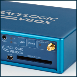
VBOX 3i systems can be used to measure braking distances to within ±2cm accuracy. It calculates parameters such as time, position, velocity, heading, height, vertical velocity and lateral/longitudinal acceleration at 100 samples per second.

VBOX can be used in all four main procedures to satisfy ECE R90 regulations:

  • Bedding (burnishing) procedure
  • Performance check
  • Brake tests (in accordance with Reg. 13 Annex. 4)
  • Cold performance equivalence and speed sensitivity tests

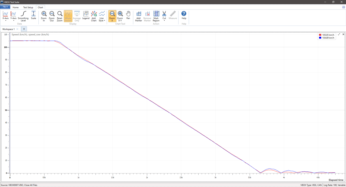
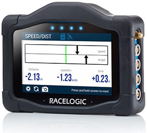
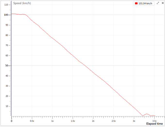
In addition to viewing results in real time via a Multi-function Display or Tablet PC, all data parameters captured using a VBOX are recorded using a Compact Flash card. All data can then be viewed using the free VBOX Test Suite software in accessible formats (e.g. graphs, charts).

ECE REGULATION R78 MOTORCYCLE BRAKE SYSTEM

With customer guidance, Racelogic created the VBTS R78 plug-in for homologation testing of motorcycles to the ECE R78 regulation. The regulation specifies the calculation of extra parameters specific to motorcycles, which are now automatically calculated by the software:

  • Start Speed
  • Braking Time
  • Braking distance
  • Average Deceleration
  • MFDD
  • Average deceleration between the 0.5 and 1 second after the brakes have been applied
  • Maximum deceleration during the brake test excluding the last 0.5s
  • Avg. brake force for the Front and Rear brakes between 80% and 10% of the specified test speed
  • Centreline Deviation
ABS TESTING AND DEVELOPMENT

VBOX test equipment enables you to accurately capture individual wheel speed signals, from either CAN or rotary encoders, high dynamic vehicle movement, and the vehicle’s straight line deviation.

BRAKE ASSIST SYSTEM TESTING AND DEVELOPEMENT

VBOX test equipment enables you to capture pedal force and travel sensor outputs via analogue inputs at 500Hz.

pattern
https://www.zenmicrosystems.co.in/wp-content/themes/blake/
https://www.zenmicrosystems.co.in//
#ef3e35
style3
paged
Loading posts...
/home/zenmicrosystemsc/public_html/
#
on
none
loading
#
Sort Gallery
https://www.zenmicrosystems.co.in/wp-content/themes/blake
on
no
off
ENTER YOUR EMAIL HERE!
off
off